Hinged-door hardware by CiiLOCK EngineeringTechnical resources

3D adjustable / direct-fix / lift-off

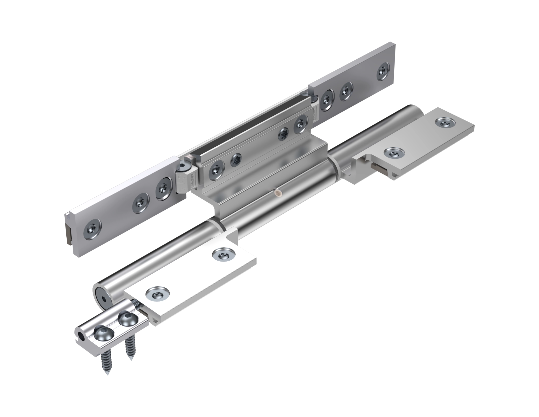
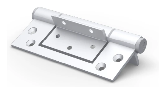
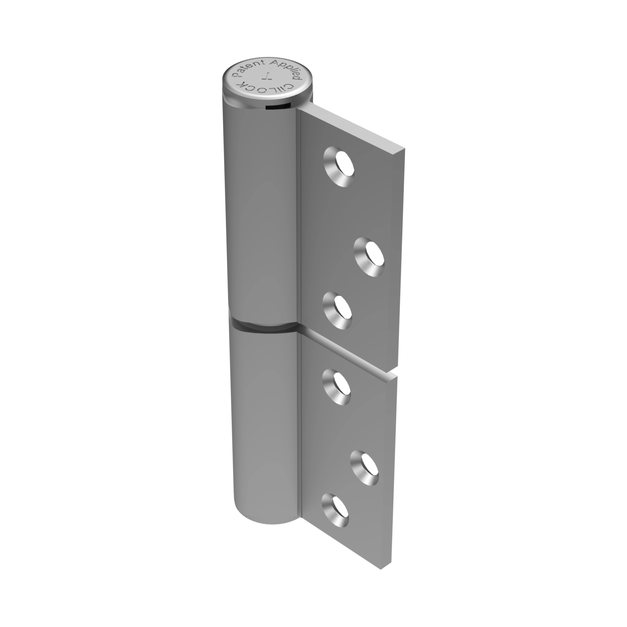
Trinity 4414

Three-direction adjustment contained within a direct screw-fixed hinge. For conventional aluminium systems without a clampable C-groove.

Adjustable hinges / 4414

3DAdjustment within the hinge
100 kgMaximum published configuration
135°Maximum opening

Product architecture

3D adjustable & direct-fix & lift-off

The adjustment mechanism is carried inside the body and knuckle. The door and jamb use direct screw fixing, without relying on a sliding leaf in a profile groove.

01

Direct screw fixing

Countersunk on both sides to suit 10g screws.

02

Lift-off architecture

Allow approximately 28-30 mm of clearance above the door for removal.

03

Three-direction correction

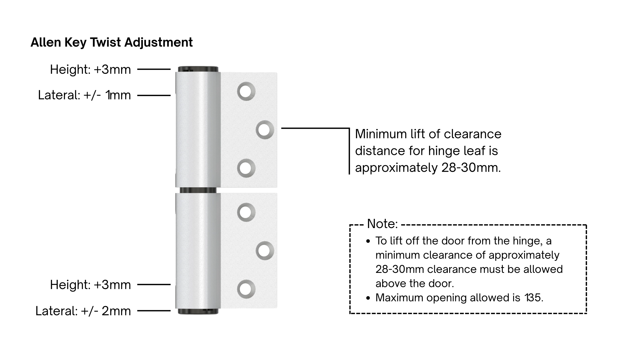
Horizontal ±2 mm, lateral ±1 mm and 6 mm total vertical travel.

Trinity / Adjustment explained

Three directions.
One hinge.

See where the adjustments act before you open the technical sheet. Use an Allen key at the designated adjustment points.

Horizontal
±2 mm
Lateral
±1 mm
Vertical
6 mm total travel

Allow approximately 28–30 mm above the door for lift-off. Maximum opening: 135°. Check 4414-C for the full configuration.

CiiLOCK Trinity adjustment illustration, identifying horizontal, lateral and height adjustment and lift-off clearance.
CiiLOCK adjustment illustration from the supplied earlier website reference. Open the image for a larger view; use the released sheet for specification.

Product demonstration

See the adjustment.

All product videos

CiiLOCK Engineering / 1:00

Trinity: three-way adjustment

CiiLOCK’s explainer for the Trinity 4414 hinge. Watch the product demonstration alongside the adjustment illustration and released drawing.

Watch on YouTube (opens in a new tab)

Play connects to YouTube. No player loads before you choose to play.
Technical data

Specify the configuration.

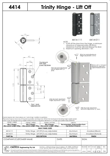
Dimensions and configurations are from the linked CiiLOCK drawing. Check the drawing and application before fabrication.

Check an application
Overall height
123 mm
Horizontal adjustment
±2 mm
Lateral adjustment
±1 mm
Vertical adjustment
±3 mm (6 mm total travel)
Maximum opening
135°
Lift-off clearance
Approximately 28-30 mm above the door

Published panel configurations

Read each row as one configuration. Do not combine independent maxima.
Minimum hinges Maximum panel H × W Maximum panel mass
2 2040 × 820 mm 50 kg
3 2040 × 820 mm 70 kg
4 2400 × 1000 mm 100 kg

Listed finish options

Part number Finish
4414-111 Black anodised
4414-011 Natural anodised

Confirm finish and availability when ordering. Images do not represent every finish.

Before specification

The drawing recommends hinge positions 140 mm from the top and bottom of the panel.

For a door closer, the drawing calls for one extra hinge, positioned near the top. Follow the complete positioning instructions in 4414-C. Test applications outside the stated configurations.

Original CiiLOCK technical sheets

Drawings for 4414.

View or download the supplied PDFs. Check the complete sheet, revision and application before fabrication. Use the separately linked installation guide where provided; contact CiiLOCK for additional CAD or application support.

Application support

Check the details with CiiLOCK.

Include the product code, panel size and mass, profile details and the required operation.

Discuss your application